How does the top fuel clutch system work (1 Viewer)

FC138fan

Nitro Member
clutch120small.jpg
clutch_09.jpg


Hearing talk about how the clutch works in another thread reminded me that I never did put together how those things work.

I am an engineer, so I think I am pretty good at figuring out how things work. Now everything in front of the bell housing makes sence - its the 4 cycle engine (a hopped up version for sure, but the principle is the same) Everything behind the bell housing makes sence (just the differential) It's that clutch that I cannot understand the mechanics of how it works. This is because no one has ever explained it so that I could understand it.

Here's my guess as to how it works (This is me putting pieces of information together and making a logical guess).

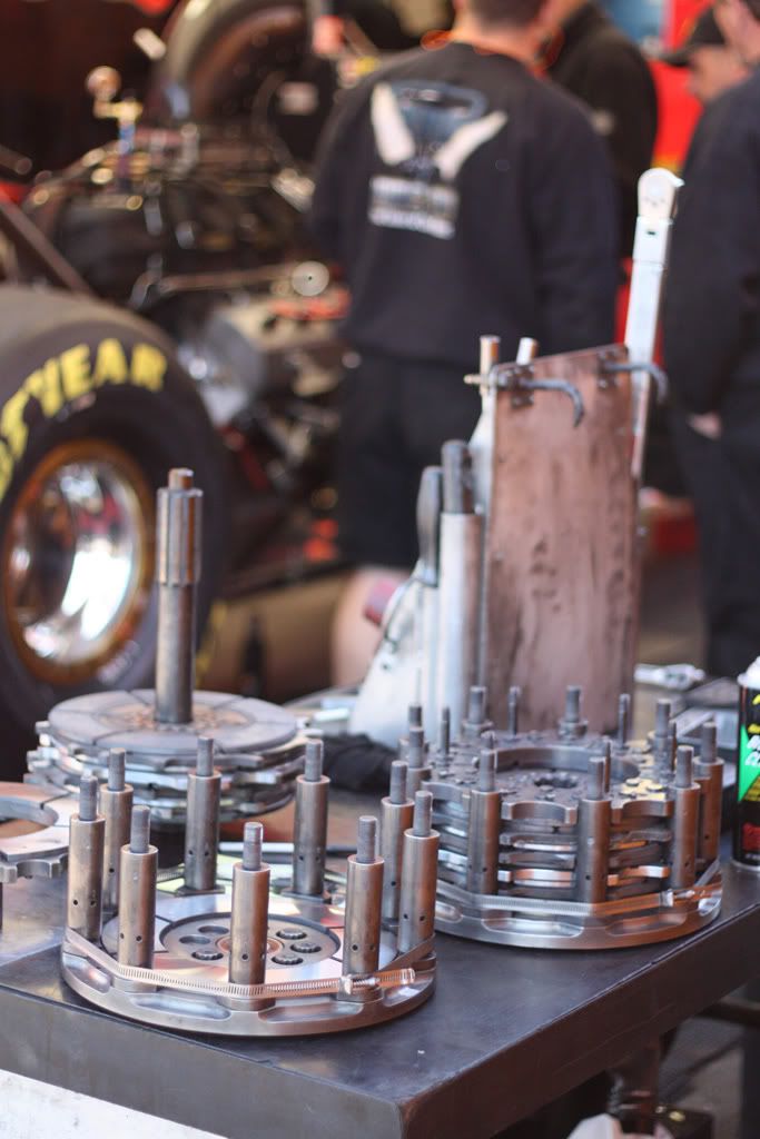
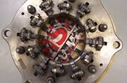
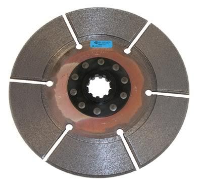
Somehow at the hit the engine goes to what 7000 rpm - the initial setup slips those disks somehow and only transfers a fraction of the rpm to the differential. As the back tires rotate faster, part of the clutch mechanism rotates faster (Im guessing thats what that left picture is) and little weights get forced out due to centripetal force. Then theres some sort of transfer of that outer force to produce pressure on the clutch disks (im guessing thats the right picture) which slowly transfers more and more RPM to the differential.

Can someone knowledgable about how this thing works write me a better and correct description?

What is it meant by a 5 stage clutch?

What is slipping the clutch?

Are there pneumatics involved with the clutch system?

Is it a smooth transfer of power to the back wheels or does it happen in stages?

Ive seen them take the bell housing off and theres the guts of the clutch system - which parts of that system rotate and which are fixed? (pics helpful)

What do other terms that are thrown around mean?

You can be technical, but not too technical. If you have your own pictures that would be helpful too.
 
That's the wrong pressure plate (left pic).
The fuel plates have 18 lever arms.

pssst... it's "centrifugal" :eek:
 
Let me caveat the following with the statement that I am not an engineer, nor I am I a clutch guy. I have never worked on a Fuel Car clutch or even really touched the components for that matter. The following is what I have learned from looking, reading and listening mixed in with a little mechanical knowledge.

A Top Fuel clutch is basically a centrifugal clutch, that has a pedal. There are a number of "fingers/levers" on the pressure plate that are weighted differently and are different height and lengths. When the RPM of the engine goes up and the clutch speeds up with it the centrifugal force on the fingers, which are mounted like a lever apply more pressure to the pressure plate reducing the clutch slip. The higher the RPM goes, the more counterweight force is transferred to the pressure plate.

There is a "ram" that stops the fingers from releasing and applying pressure, this ram is controlled pneumatically (I think is bleeds air pressure) and is activated when the throttle is hit on the line. Keep in mind that when a Top Fule/Funny Car is on the line fully staged, the clutch pedal is already out and the clearance of the clutch plates allows it to slip and the driver can hold the car still on the brake.

When the driver hits the throttle the RPM of the engine goes up drastically and the fingers/levers on the pressure plate that are not stopped by the ram apply more pressure to the clutch and drive the car forward. The ram moves at a predetermined rate and allows more and more fingers to apply pressure as the car goes down the track causing it to eventually be at 1:1 with the engine.

In simple terms, it is like taking off in 5th gear with a standard transmission, but instead of gradually releasing the clutch pedal with your foot to apply more and more pressure to the clutch, the slippage is controlled by the "ram" allowing more and more pressure to be applied to the clutch.

Keep in mind that they have to let the clutch slip so that it doesn't spin the tires as they have enough power even to do this at a 1:1 drive ratio (same at top gear), where as in a car you would slip the clutch so that the engine didn't stall as it doesn't have enough power to overcome the load on the engine.

I am not sure that I have heard the term “5-stage” before when referring to the clutch, but it is most likely to refer to the 5 disc clutches that they teams use. There are 5 clutch plates and floaters between the plates.

“Slipping the Clutch” is a reference to a state where the engine RPM is greater than that of the clutch output RPM. This is at any point during the run before the clutch has completely locked up and the engine and clutch output RPM are the same.

The entire clutch assembly rotates with no parts being “fixed” with the exception of the bell housing. When the car is sitting on the line fully staged the clutch plates are not spinning, they are sitting on the spline of the output shaft. The clutch stand is rotating at engine speed at all times as it is connected to the crankshaft.

Coupled with the application of the clutch the fuel system needs to be set up so that the engine has just the right amount of fuel to support the application of the clutch but not too much so that it drops a cylinder then loses power and the clutch pulls the engine down etc.
 
Last edited:
There is a "ram" that stops the fingers from releasing and applying pressure, this ram is controlled pneumatically (I think is bleeds air pressure) and is activated when the throttle is hit on the line. Keep in mind that when a Top Fule/Funny Car is on the line fully staged, the clutch pedal is already out and the clearance of the clutch plates allows it to slip and the driver can hold the car still on the brake.

When the driver hits the throttle the RPM of the engine goes up drastically and the fingers/levers on the pressure plate that are not stopped by the ram apply more pressure to the clutch and drive the car forward. The ram moves at a predetermined rate and allows more and more fingers to apply pressure as the car goes down the track causing it to eventually be at 1:1 with the engine.


Great explanation. It's hard to explain to newbies exactly how the clutch slippage is controlled and I think you've nailed it right on with easy to understand lingo.
 
Doesn't Rockwell in disk material have allot to do with the engagement. we used to run between 40 and 60 in the NFT car.
 
Let me caveat the following with the statement that I am not an engineer, nor I am I a clutch guy. I have never worked on a Fuel Car clutch or even really touched the components for that matter. The following is what I have learned from looking, reading and listening mixed in with a little mechanical knowledge.

A Top Fuel clutch is basically a centrifugal clutch, that has a pedal. There are a number of "fingers/levers" on the pressure plate that are weighted differently and are different height and lengths. When the RPM of the engine goes up and the clutch speeds up with it the centrifugal force on the fingers, which are mounted like a lever apply more pressure to the pressure plate reducing the clutch slip. The higher the RPM goes, the more counterweight force is transferred to the pressure plate.

There is a "ram" that stops the fingers from releasing and applying pressure, this ram is controlled pneumatically (I think is bleeds air pressure) and is activated when the throttle is hit on the line. Keep in mind that when a Top Fule/Funny Car is on the line fully staged, the clutch pedal is already out and the clearance of the clutch plates allows it to slip and the driver can hold the car still on the brake.

When the driver hits the throttle the RPM of the engine goes up drastically and the fingers/levers on the pressure plate that are not stopped by the ram apply more pressure to the clutch and drive the car forward. The ram moves at a predetermined rate and allows more and more fingers to apply pressure as the car goes down the track causing it to eventually be at 1:1 with the engine.

In simple terms, it is like taking off in 5th gear with a standard transmission, but instead of gradually releasing the clutch pedal with your foot to apply more and more pressure to the clutch, the slippage is controlled by the "ram" allowing more and more pressure to be applied to the clutch.

Keep in mind that they have to let the clutch slip so that it doesn't spin the tires as they have enough power even to do this at a 1:1 drive ratio (same at top gear), where as in a car you would slip the clutch so that the engine didn't stall as it doesn't have enough power to overcome the load on the engine.

I am not sure that I have heard the term “5-stage” before when referring to the clutch, but it is most likely to refer to the 5 disc clutches that they teams use. There are 5 clutch plates and floaters between the plates.

“Slipping the Clutch” is a reference to a state where the engine RPM is greater than that of the clutch output RPM. This is at any point during the run before the clutch has completely locked up and the engine and clutch output RPM are the same.

The entire clutch assembly rotates with no parts being “fixed” with the exception of the bell housing. When the car is sitting on the line fully staged the clutch plates are not spinning, they are sitting on the spline of the output shaft. The clutch stand is rotating at engine speed at all times as it is connected to the crankshaft.

Coupled with the application of the clutch the fuel system needs to be set up so that the engine has just the right amount of fuel to support the application of the clutch but not too much so that it drops a cylinder then loses power and the clutch pulls the engine down etc.

Wow, Paul, you're not as thought as I dumb you are.:D Well explained, enough so for a Swede like me to understand.
 
When we put enough little pieces together . . . :D

Our setup had a bunch of little poppets that were on a timer and it uses compressed co2 . . . there's a whole process to it as well.

We spin the tires to simulate the burnout, then andy and richard have several steps they run through.

I am not the clutch guy obviously . . . I am around to watch the clutch process but it isn't my job to surface the discs/install/service the trans.
 
thank you for the great description. I appreciate everyones input. I have supplementary q's though. good luck!

does anyone have an exploded diagram of the clutch pack?

"5 clutch plates and floaters" what is the purpose of the floater? what does a clutch plate and a floater look like? what two surfaces press together to create the friction to lock eventually into 1 to 1?

is there 1 master plate containing the finger levers? is this located at the front or back of the bell housing?

why have 5 clutch discs over 4.. or 3... or 6?

can that "ram" push the finger levers off the plates to take power away during a run?

why not just use all pneumatics to apply pressure? why use a "third party" finger lever?
 
The floaters provide a surface for each disc to lock up with. The floaters are held in place by the stands on the flywheel studs. They have groves in them that help with the wear of the discs.

The "hat" (pressure plate) holds all of the "fingers" and is held in place by the same studs as the floaters. The flywheel, floaters, discs, and hat all lock together to achieve 1:1. You can tell by the tone of the engine as the car goes down the track when the happens.

The number of discs have changed over the years to try and managed getting the horsepower to the ground. The rockwell of the discs will determine how much wear the discs will have during a run. The softer the disc the higher the wear and the harder the disc the lower the wear.

The cannon (ram) is cocked by pneumatics that bleed off liquid to allow the levers to increase the pressure on the discs as centrifugal force increases. It only moves to allow application of the clutch based on how the timers are adjusted. The cannon can be sped up or slowed down to adapt to changing track/weather conditions.

I could go on for pages, but that is the basics of how it works.
 
does anyone have an exploded diagram of the clutch pack?

I don't have an expoded version, but I did get this shot at Houston earlier this year.

IMG_4988.jpg


"5 clutch plates and floaters" what is the purpose of the floater? what does a clutch plate and a floater look like? what two surfaces press together to create the friction to lock eventually into 1 to 1?

The "floaters" are the plates that sit between the clutch plates, they locate on the towers that are on the flywheel. The floaters and the clutch plates are pressed against each other as the levers apply force to the pressure plate, this transfers the power from the floater, to the clutch plate.

In the photo above the floaters are the parts of the "sandwich" that look like a cog/sprocket.

Here is a pic of a clutch plate

phpThumbbffa.jpg


Here is a pic of a floater

phpThumbfd9f.jpg


is there 1 master plate containing the finger levers? is this located at the front or back of the bell housing?

The "master plate" that contains the fingers/levers is the pressur plate, which is located at the rear of the bell housing. The pressure plate is not installed on the clutch pack in the above photo.

This is what a pressure plate/hat looks like

phpThumb222e.jpg


why have 5 clutch discs over 4.. or 3... or 6?

Initially clutches were single plate units that were more of a standard design. Over time they have added discs and the centrifugal assistance. By increasing the number of plates you can apply the pressure over a greater surface area. I would expect that this would give you a more consistent result, smoother appication as the fingers are released and it also helps greatly in heat dissipation.

The length of the clutchpack is also imprtant as it affects bell housing length. Add more plates and the pack gets taller/longer. This will require the engine to be moved further forward in the chassis and would affect the cars front/rear weight distribution.

can that "ram" push the finger levers off the plates to take power away during a run?

No, once the fingers are released, they are released. I think that the modern clutch systems can slow the ram down or stop it if the driver gets off the gas pedal so that the clutch doesnt continue to engage in a tire spin scenario, this aids the driver in getting back on the throttle succesfully and regaining traction.

why not just use all pneumatics to apply pressure? why use a "third party" finger lever?

I am not sure.

I would hazard a guess to say that it has something to do with the amount of pressure that is required to be applied to the pressure plate to lock the clutch up. The mechanical route currently used may actually be simpler ad just as effective.

Check out Boninfante Performace Clutch Parts Website for more pics.
 
Last edited:
There is a "ram" that stops the fingers from releasing and applying pressure, this ram is controlled pneumatically (I think is bleeds air pressure) and is activated when the throttle is hit on the line. Keep in mind that when a Top Fule/Funny Car is on the line fully staged, the clutch pedal is already out and the clearance of the clutch plates allows it to slip and the driver can hold the car still on the brake.

When the driver hits the throttle the RPM of the engine goes up drastically and the fingers/levers on the pressure plate that are not stopped by the ram apply more pressure to the clutch and drive the car forward. The ram moves at a predetermined rate and allows more and more fingers to apply pressure as the car goes down the track causing it to eventually be at 1:1 with the engine.


Great explanation. It's hard to explain to newbies exactly how the clutch slippage is controlled and I think you've nailed it right on with easy to understand lingo.

The throw out bearing is actually held hydraulically. The air timers are controlling the amount of "bleed" on the the cannon, or the piston that is holding the throw out bearing forward. There is a air switch under the throttle pedal that is depressed when it is pressed all the way down at the hit. As soon as it is switched on, it activates the clutch timer system, as well as fuel and ignition systems. Idle speed is very important as a lower idle rpm will not allow the engine to get to desired rpm at the hit, so the clutch will not have proper clamping force do to insuffiecent lever angle. Too much, and the opposite problem, too aggressive at the hit. I am pretty sure if I remember correctly, the Rpm at the hit is more like 8200 or so. Depending on how the clutch is set up it leaves on 6 primary levers with weight that is varied according to track temp. That is the adjustment you see a clutch guy doing last minute in the staging lanes when he has the lid off the can. I would do changes with as little as 2 pair in front of us. Once the timer starts, it lets the cannon move rearward, thus moving the throw out bearing back. The secondary levers are staggered in height, with #1 coming in first, then #2, and so on. These levers have weight on them also. As they apply they add more and more clamping force. As the pack wears, it allows the levers to stand up more, or get more angle, also adding more clamp load. There are different radius levers, different widths (lever weighs more) and different weights to put on them. Crew chief preference and something that is tested at different tracks. We had different weight configurations for different track conditions. A tight track with cool weather (Friday nite) would get alot more secondary weight then our race day configuration. Primary weight is only changed by track temp. Usually 5 degree difference would equal adding or removing one nut (a half nut that weighs 3.2 grams). There is much more in depth going on in the clutch department, but that is about as simple as I can make it.
PS
The rockwell # on the disc is important as it gives an indication of how the disc will wear. A lower rockwell # means a softer disc which should wear more than a higher # or harder disc. The packs are laid out by rockwell # and the date stamp on the disc.
 
Last edited:
why not just use all pneumatics to apply pressure? why use a "third party" finger lever?

Clayton Harris worked with Bob Brooks to develop that type of system. (late 80's)
It wasn't consistent due to not being tied to engine rpm ,with computer control it would have worked ,but that is illegal.
 
the TV show Modern Marvels had an hour on drag racing - episode 159 from 2002, I think?

This show or a similar one on the cable science channels had an excellent computer graphics animation of the modern dragster clutch.

"air timers" - now that's a bit of nitro tech I could use some schooling on! I've never been able to find out who makes them, anyway!

-90% Jimmy

thanks for the above insights. we've got some maters that would make good tech writers!
 
Im trying to digest this amount of info. This is great, thanks for the information. Now more questions. Excuese me if I sound dumb for not understanding, as I have never seen one of these things work.

If I understand...

The floaters and master plate with the levers are attached to a flywheel which is attached to the rear wheel driveshaft. The clutch plates are attached to the crankshaft and are sandwiched between these floaters.

The fingers apply a clamping force to the floater / clutch disk sandwich that lock the flywheel and crankshaft eventually to 1 to 1. The fingers apply force according to the rear wheel RPM.

I am confused with this pneumatic ram thing... It sounds like this ram controls the levers on the back of the pack, as it slides out the levers engage but I just thought the levers are controlled by the rear wheel RPM?

These levers, are they controlled pneumatically by the ram or by the centripetal force of the rear RPM, or both? How does the engine RMP get maintained at 5000 - 6000 or whatever as it goes down track?
 
The floaters and master plate with the levers are attached to a flywheel which is attached to the rear wheel driveshaft. The clutch plates are attached to the crankshaft and are sandwiched between these floaters.

Not quite. The flywheel bolts up to the crankshaft. The floaters and pressure plate/hat/master plate are all connected to the flywheel. The clutch plates are sandwiched between the floaters. Although they are located between the floaters they are not actually "connected" to the flywheel at all, they locate on the spline of the drive shaft.

The fingers apply a clamping force to the floater / clutch disk sandwich that lock the flywheel and crankshaft eventually to 1 to 1. The fingers apply force according to the rear wheel RPM.

Not quite. As the flywheel is bolted to the crankshaft the flywheel, floaters and pressure plate/hat/master plate are always at 1:1 with engine RPM, it is the clutch discs that are not always at 1:1.

The fingers apply varying amounts of force based on ENGINE RPM. As the engine RPM goes up the amount of force generated by the “free” levers/fingers is increased and as a result the clamping pressure on the clutch pack is increased. This reduces the amount of slip the clutch plates have in relation to the floaters and the clutch plate speed increases accordingly. The clutch plates locate on the drive/output shaft spline, so as the clamping pressure on the clutch pack is increased and the RPM of the clutch plates increase this is transferred to the rear wheels via the output shaft which results in rear wheel acceleration/increased wheelspeed.

I am confused with this pneumatic ram thing... It sounds like this ram controls the levers on the back of the pack, as it slides out the levers engage but I just thought the levers are controlled by the rear wheel RPM?

The purpose of the ram is to stage/time the activation of all of the fingers. As the ram moves it gradually releases fingers/levers due to the different height/length of each finger/lever. This allows the gradual application of all of the fingers/levers as the car goes down the track. Engine RPM controls the amount of force generated by the fingers/levers, the ram (canon) position controls how many levers/fingers have been released, therefor the amount of pressure being applied to the clutch pack.

These levers, are they controlled pneumatically by the ram or by the centripetal force of the rear RPM, or both? How does the engine RMP get maintained at 5000 - 6000 or whatever as it goes down track?

The levers are controlled by two things:

1 – The ram. As the ram moves out of the way, it gradually releases the fingers/levers (depending on their length/height) so that they can apply pressure to the clutch pack.

2 – Centrifugal Force (Centripetal Force is different). Depending on the weight and length of the finger and the RPM of the engine it applies varying amounts of pressure to the clutch pack once the ram has allowed it to be released.

The engine maintains its RPM by the gradual application of the clutch. The crew chief has a desired RPM range that they want to keep the car in during the run. As the car leaves the line there is a lot of clutch slippage, as the car accelerates the natural result is for engine RPM to increase, but as the amount of pressure on the clutch pack is increased (due to the release and application of the fingers/levers) it puts more load on the motor, this keeps the RPM from continuing to increase outside of the rate the Crew Chief would like (theoretically this is like gradually shifting into higher gears with a regular transmission).

Once the clutch is fully locked up the RPM of the engine will start to increase as the car accelerates to the finish line.
 
Last edited:
Wow, that last post did it. Now I think I understand -

The engine idles - the flywheel, floaters, and master plate with the levers on it spin at the idle RMP, I'd imagine no fingers are spinning fast enough to apply pressure to the clutch, so when the driver lets off the clutch pedal and holds the brake just before green, not enough clamping force is down... just enough to pull the RPMs down a bit as they turn the fuel to full. At this time the clutch disks are stationary as the rear wheels are not rotating.

At the hit, the RPM goes to 5000-8000, as do the flywheel, floaters and master plate. This spinning forces the levers that are long (or short) enough to apply some clamping force to the sandwich, transferring that rotational motion to the driveshaft and rear tires.

At this time the piston keeping the shorter (or longer) levers from applying pressure to the clutch sandwich begins to slide out using pneumatics (or hydraulics) at a pre programmed rate determined in the pits. As the run goes on and the piston slides out, it releases levers onto the clutch sandwich applying more pressure to the clutch sandwich as it goes down track, eventually locking the clutch disks and flywheel at 1 to 1.

Sound right?

That sounds difficult. There are alot of things in there that can change. If everything isnt exactly the same every time then that system can be unreliable. Throw in power tuning, timing, fuel, wing angles and all the other ****..

I guess a good set of notes and reliable parts go a long way.

What a fun job it would be to have the time and money to figure those things out.
 
Wow, that last post did it. Now I think I understand -

The engine idles - the flywheel, floaters, and master plate with the levers on it spin at the idle RMP, I'd imagine no fingers are spinning fast enough to apply pressure to the clutch, so when the driver lets off the clutch pedal and holds the brake just before green, not enough clamping force is down... just enough to pull the RPMs down a bit as they turn the fuel to full. At this time the clutch disks are stationary as the rear wheels are not rotating.

At the hit, the RPM goes to 5000-8000, as do the flywheel, floaters and master plate. This spinning forces the levers that are long (or short) enough to apply some clamping force to the sandwich, transferring that rotational motion to the driveshaft and rear tires.

At this time the piston keeping the shorter (or longer) levers from applying pressure to the clutch sandwich begins to slide out using pneumatics (or hydraulics) at a pre programmed rate determined in the pits. As the run goes on and the piston slides out, it releases levers onto the clutch sandwich applying more pressure to the clutch sandwich as it goes down track, eventually locking the clutch disks and flywheel at 1 to 1.

Sound right?
That's it in a nutshell!
punk.gif

.
 
Not quite. The flywheel bolts up to the crankshaft. The floaters and pressure plate/hat/master plate are all connected to the flywheel. The clutch plates are sandwiched between the floaters. Although they are located between the floaters they are not actually "connected" to the flywheel at all, they locate on the spline of the drive shaft.


Input shaft :D
 
Ways To Support Nitromater

Users who are viewing this thread


Back
Top